
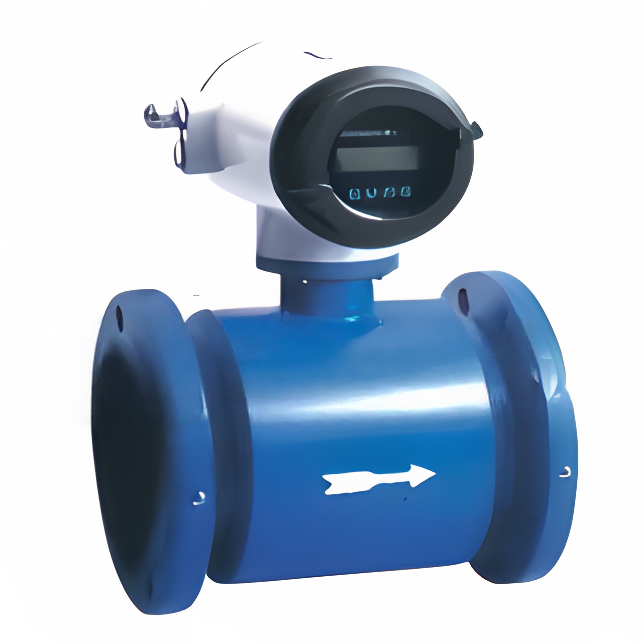
Product Features:
-
Measurement is not affected by changes in fluid density, viscosity, temperature, pressure, or conductivity.
-
The measuring tube has no obstructing moving parts, resulting in no pressure loss and low requirements for straight pipe sections.
-
The series is available in nominal diameters from DN15 to DN3000, with various options for liner and electrode materials.
-
The converter adopts a novel excitation method, featuring low power consumption, stable output, and high accuracy. The flow rangeability can reach up to 1500:1.
-
The converter can be combined with the sensor as a compact (integral) or remote (separate) type.
-
The converter employs a 16-bit microprocessor with a 2×16 LCD display, allowing convenient parameter setting and programming.
-
The flowmeter features a bidirectional measurement system with three built-in totalizers: forward total, reverse total, and net total (difference). It can display instantaneous flow rate and totalized flow, and offers multiple outputs: current, pulse, digital communication, and HART.
-
The converter uses Surface Mount Technology (SMT) and incorporates self-checking and self-diagnostic functions.
JHLD Series Electromagnetic Flowmeter Selection Guide
◆ Range Confirmation
For general industrial electromagnetic flowmeters, the recommended flow velocity of the measured medium is 2 to 4 m/s. Under special circumstances, the velocity should be no less than 0.2 m/s and no greater than 8 m/s. If the medium contains solid particles, the typical velocity should be less than 3 m/s to avoid excessive wear on the liner and electrodes. For viscous fluids, a velocity greater than 2 m/s is recommended, as a higher flow velocity helps to automatically remove viscous deposits on the electrodes, thereby facilitating accurate measurement.
Once the flow range Q is determined, the meter size D can be selected based on the velocity range V mentioned above, calculated using the following formula:
Q = πD²V/4
Where: Q — Flow rate (m³/h); D — Pipe inner diameter (m); V — Flow velocity (m/h)
The flowmeter range Q should be greater than the expected flow rate, and the normal operating flow rate should preferably be slightly greater than 50% of the full-scale range of the flowmeter.